
I nostri Prodotti
Prodotti e soluzioni dalle tecnologie avanzate
SDG S.r.l. distribuisce macchine per la produzione e l’assemblaggio di circuiti stampati (PCB) con tecnologia SMT ad ogni settore.

Printer
Massima qualità e
prestazioni con la massima flessibilità.

Cleaning Process
Massima purezza ed eliminazione di qualsiasi impurità.

Pick&Place
Maggiore precisione
e minori sprechi.

Software solution
Software più intelligenti per una maggiore efficienza.
La nostra Storia
Storia. Missione. Innovazione.
SDG S.r.l. è una realtà creata da un gruppo di professionisti che collabora da molti anni
con i primari fornitori europei di apparecchiature per la produzione elettronica.


News
Novità di SDG
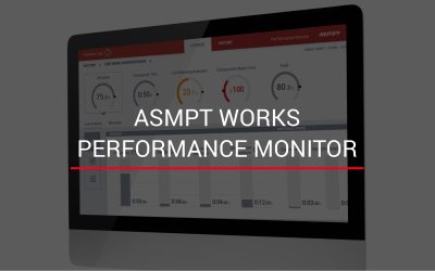
ASMPT Works – Performance Monitor
Non dovrebbero tutti gli addetti alla produzione avere la stessa mentalità KPI e sapere se sei sulla strada del successo?ASMPT Works - Performance Monitor Implementare Kanban è semplice utilizzando il nostro WORKS Performance Monitor (APM) che mostra i KPI più...
SDG è alla Ricerca di un Tecnico Installatore da inserire nel proprio team
Invia la tua candidatura, clicca sul pulsante e compila il formSDG, azienda leader nella distribuzione di macchinari per l’elettronica nel settore Surface-Mount-Technology (SMT), da anni collaboriamo con i primari fornitori europei di apparecchiature per il mercato...
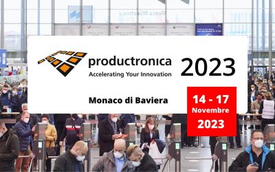
SDG partecipa alla fiera Productronica 2023
Dal 14 al 17 Novembre a Monaco di BavieraSDG sarà presente presso gli stands dei brands da lei distribuiti ASMPT - ASYS - REHM - DCT - GÖPEL - CyberOptics e sarà sempre pronta a supportare i suoi clienti.Per fissare un appuntamento con i nostri venditoriIl TEAM SDG...
I nostri Servizi
Supporto tecnico
SDG S.r.l. è sempre a disposizione per fornire
un supporto tempestivo e preciso.